ESP32PICOの機材で、CANコントローラ機能を使えると知り、CAN通信を試してみました。
なお、ESP32におけるCANコントローラは、TWAI(The Two-Wire Automotive Interface) というペリフェラルがCANプロトコルと対応しているようです。
ESP32-PICO-D4のデータシートから、TWAI対応であることが読み取れます。
準備
必要なモノ
実験に必要な機材、ソフトウェアを示します。
Hardware
- M5StickC Plus / M5Stack社
- M5Stack用CAN-BUSユニット(CA-IS3050G)
- USB CAN Module / InnoMaker
- Windows PC
実験
今回試した回路を示します。
ブレッドボードをCANバスとして設定しました。
>
○ CANバスの終端抵抗
- InnoMakerのCAN BUSモジュール側 : ジャンパピンを設定することで、基板上の120Ωの抵抗を有効
- M5Stick側 : M5 CAN-BUS Unitに付属の120Ωのカーボン抵抗をブレッドボードに刺し、有効
○ CAN通信の設定
今回の通信速度(baudrate)は500kbpsとしました。
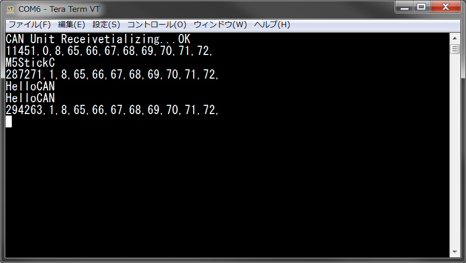
○ 通信確認
- M5StickC側
M5-Product-Example-CodeのCAN受信、CAN送信プログラムを参考にしました。
//Insert CAN Unit to PORT-B,if received message, screen will display

#include "M5StickCPlus.h"
#include "ESP32CAN.h"
#include "CAN_config.h"

#define TX_PORT GPIO_NUM_32 // 使用するデバイスのGPIOにあわせてください
                                                     // この設定は、M5StickC plusのGroveポートを使用した場合の設定です。
#define RX_PORT GPIO_NUM_33 // 使用するデバイスのGPIOにあわせてください
                                                     // この設定は、M5StickC plusのGroveポートを使用した場合の設定です。

CAN_device_t CAN_cfg;

void header(const char *string, uint16_t color)
{
    M5.Lcd.fillScreen(color);
    M5.Lcd.setTextSize(1);
    M5.Lcd.setTextColor(TFT_WHITE, TFT_BLACK);
    M5.Lcd.fillRect(0, 0, 320, 30, TFT_BLACK);
    M5.Lcd.setTextDatum(TC_DATUM);
    M5.Lcd.drawString(string, 160, 3, 4);
}


void setup() {
    M5.begin();
    Serial.begin(115200);
    M5.Lcd.setRotation(1);
    Serial.println("CAN Unit Receive");
    header("CAN-Bus Receive", BLACK);

    CAN_cfg.speed=CAN_SPEED_500KBPS;                               // ここでボーレートを設定します
    CAN_cfg.tx_pin_id = TX_PORT;
    CAN_cfg.rx_pin_id = RX_PORT;
    CAN_cfg.rx_queue = xQueueCreate(10,sizeof(CAN_frame_t));
    //start CAN Module
    ESP32Can.CANInit();
}

void loop() {
  CAN_frame_t rx_frame;
  CAN_frame_t tx_frame;

  //キューからCANフレームを受信する
  if(xQueueReceive(CAN_cfg.rx_queue,&rx_frame, 3*portTICK_PERIOD_MS)==pdTRUE){

    Serial.print(millis());   // 受信時間
    Serial.print(",");
    Serial.print(rx_frame.MsgID,HEX);   // Msg ID
    Serial.print(",");
    Serial.print(rx_frame.FIR.B.DLC);   // DLC
    Serial.print(",");

    for(int i = 0; i < 8; i++){
      Serial.print(rx_frame.data.u8[i],HEX);   // CANデータ
      Serial.print(",");
    }
    printf("\n");
  }else{
    // データを送信します
    M5.update();
    if (M5.BtnB.isPressed())
    {
        tx_frame.FIR.B.FF = CAN_frame_std;
        tx_frame.MsgID = 1;
        tx_frame.FIR.B.DLC = 8;
        tx_frame.data.u8[0] = 'H';
        tx_frame.data.u8[1] = 'e';
        tx_frame.data.u8[2] = 'l';
        tx_frame.data.u8[3] = 'l';
        tx_frame.data.u8[4] = 'o';
        tx_frame.data.u8[5] = 'C';
        tx_frame.data.u8[6] = 'A';
        tx_frame.data.u8[7] = 'N';

        ESP32Can.CANWriteFrame(&tx_frame);
        //M5.Lcd.println("Send Message");
        Serial.printf("%s\n",tx_frame.data.u8);
        delay(200);
    }else if(M5.BtnA.isPressed()){
        tx_frame.FIR.B.FF = CAN_frame_std;
        tx_frame.MsgID = 1;
        tx_frame.FIR.B.DLC = 8;
        tx_frame.data.u8[0] = 'M';
        tx_frame.data.u8[1] = '5';
        tx_frame.data.u8[2] = 'S';
        tx_frame.data.u8[3] = 't';
        tx_frame.data.u8[4] = 'i';
        tx_frame.data.u8[5] = 'c';
        tx_frame.data.u8[6] = 'k';
        tx_frame.data.u8[7] = 'C';

        ESP32Can.CANWriteFrame(&tx_frame);
        //M5.Lcd.println("Send Message");
        Serial.printf("%s\n",tx_frame.data.u8);
        delay(200);
    }
  }
}
実験結果
- USB CAN Bus Module側

まとめ
Windows PC、M5StickC plus、M5 CANBUS Unitを使い、CAN通信を行えることを確認しました。